Beiträge von lsuess

    Images:


    Here is a screen-capture from Matt Moses paper showing the quite elegant system geometry that has been chosen there.
    This would need some significant change for becoming suitable for nanoscale physics and for becoming actually viable at the macroscale.
    For details on that please follow the links in bold I provided precedingly.


    Also here's a rough (also still quite conceptual) sketch of one possible robotics geometry resulting from a large number of design constraints. Details also discussed where the links point to.

    Don't take this too seriously though. It's juts good to have at least one high level conceptual vision for concrete geometry in order to spread the general idea in a memorable way.


    ~FIN~ for now

    Contributing


    I'm all ears for realistic ideas about for ways of fund this work.

    Such that the (not easy to explain) core values do not get lost.

    Like ReChain devolving into just yet another frame system that's

    not longer useful for future advanced gemstone based nanosystems.


    Also interested in hearing productive feedback.

    And maybe even receiving some 3D modelling help.

    I do all 3D modelling programatically in OpenSCAD, hoping that this eventually

    will allow for parametrically reconfigurable systems way beyond what

    (proprietary) graphical UI point & click 3D modelling tools could ever do.

    See: http://apm.bplaced.net/w/index…_as_dumbed_down_functions

    Let's go back to the bigger picture.


    In the context of future gemstone metamaterial on-chip nanofactories.

    This is mainly about the second assembly level (likely a layer in stack on a chip).

    That is the prototyping here is not about the piezomechanosynthesis

    of the base parts in the first assembly level but rather it is about

    the pick and place assembly of the already pre-made parts (crystolecule parts).

    Second assembly level:


    Umbrella project


    Even more generally I have the umbrella project

    ReMec (for Reusable mechanical components).


    ReMec also includes mechanical analogons to electrical standard components

    ( springs <~> capacitors, and such )

    ( some details here: http://apm.bplaced.net/w/index…electrical_correspondence )


    ReMec also includes parts for the first assembly level. Like wedge parts for semi hard-coding mill style standard part mass piezomechanosynthesis.

    Though these design efforts are all not really useful at the macroscale. I mean one can do mechanical pulse with modulation and buck conversion at the macroscale, yes, but beyond educative value there is rather little point in doing so.

    ( Kinda like this cool little educational kit here: https://www.kickstarter.com/pr…build-mechanical-circuits )

    If you want to read more about the basic ideas of the project

    then I have some introductory pages on RepRec and ReChain online.

    Each in the context of atomically precise manufacturing and the context of RepRap. See:

    – RepRec (nano): http://apm.bplaced.net/w/index…-and-place_robots_(GemGum)

    – ReChain (nano): http://apm.bplaced.net/w/index…tle=ReChain_frame_systems

    – RepRec (macro): https://reprap.org/wiki/RepRec_Pick_&_Place_Robots

    – ReChain (macro): https://reprap.org/wiki/ReChain_Frame_System


    Here's a very early ReChain strut prototype that I've published recently. Much to fix and improve.

    https://www.printables.com/mod…rechain-strut-prototype-1

    I still have most of the work I've done so far not published yet on a local desktop wiki.

    Macroscale usefulness too (sub-project)


    Yes, This is future backward preparatory work ...


    I still put this under the category of "near term pathways" as it
    is something we can do experimental work on today.
    And even easily and cheaply.


    While the whole project is dauntingly ambitious, I've managed to identify and split off

    a sub-project that is much more likely to succeed early. The frame system.

    As a modularly extensible frame system is an essentially necessary core part or any RepRec system.


    I call it the ReChain (sub)project.

    More on the naming later.


    You may be wondering:

    What's so special about yet another frame system? 🥱 Yawn.

    There were many inventors inventing new frame systems.

    So isn't this just yet another frame system among dozens if not hundreds?


    I'd argue no.
    I'd argue I found something fundamentally new and revolutionary here.

    Remember the focus on conservative design for the nanoscale that I've mentioned before?

    This leads to quite peculiar design constraints that you'll see nowhere else.

    And a lot of these design constraints already manifest in the sub-project of the frame system.

    That is: The ReChain project is already embodying a lot of the consequences of nanoscale design constraints.

    No need to go all the way to RepRec to see a lot of this.


    Concretely:

    – assuming zero static friction and thus opting to positively lock absolutely everything

    – averting the need for (at the lower physical size limit necessarily big) screws at every connection by employing form closure in combination with pretensioning

    – generous tolerance self centering for all interfaces

    – and a few more


    I think of ReChain frame systems as a whole class.

    Just like I think of RepRec systems and RepRap printers as a whole class.


    A nice aspect of ReChain frame systems is that they could potentially become useful at the macroscale too.

    You may argue that the conservative design constraint for the nanoscale will clearly mismatch ideal designs for the macroscale at least in some regards. And you may be right.

    Surprisingly I found that this is barely the case though.

    Especially for fully FFF-printed systems trying to avert factory made fine detail carrying metal screws and metal ball bearings.
    Which was/is a goal of the RepRap project. Minimizing non-locally factory made vitamin components.


    ReChain … Re stands for both reusability and
    for rebar as in pre-tensioned concrete, but a removable chain instead of irreversibly embedded metal rods.

    The project


    I call this project the RepRec project.

    – for Replicating Recomposers … pointing to part recomosability and recyclability

    – in naming analogy to project RepRap

    The idea is to demonstrate a distributed self replicative robotic system.

    Not ultra compact in a self contained free floating box.

    So this is quite unlike the outdated molecular assembler concept.

    Rather similar to what Matt Moses demonstrated 2014 in the paper:

    "An architecture for universal construction via modular robotic components"

    https://rpk.lcsr.jhu.edu/wp-content/uploads/2014/08/Moses13_An-Architecture.pdf

    … but with more focus on actual productivity. Not just self replication for the sake of self replication.

    That is: Systems need to be …

    – designed such that they can operate reasonably fast and

    – capable of producing products that do not carrying too much system artifacts into the product

    (unlike LEGO which carries anisotropy and usually too much surface jaggedness into it's products).


    Here is an image showing the idea conceptually.

    Prototyping macroscopically (bulk limit) but such that the ideas can eventually be

    relatively easily translated into atomically precise atomistic designs.

    Actual designs will likely feature quite a bit more atoms per base part than in this conceptual illustration.


    Nanoscale physics aware macroscale engineering


    Regarding the concern that structures would just not be stiff enough.

    The concern of "falling material stiffness with scale" …

    ( Math: http://apm.bplaced.net/w/index…ness_of_smaller_machinery )

    Coming from the suppression of thermal motions in mechanosynthesis point of view

    I was initially (quite mistakenly) worried that macroscale style machinery at the nanoscale might not provide enough stiffness as it's not designed sturdy enough in choice of geometries.


    But regarding deflections form accelerations from motions for pick-and-place assembly working it out I found that
    falling stiffness and falling mass exactly cancel each out for scale-natural-machine operation frequencies (i.e. constant absolute speed across scales).

    See here for the math: http://apm.bplaced.net/w/index…deflections_across_scales

    Beyond that …

    – one wants to go slower (for lowering friction losses) and

    – one does get way better material properties (flawless nano-gem >10% bendable).

    So effectively using FFF printed plastic is an excessively conservative constraint. So much so that it may lead to quite excessive overengineering for the nanoscale which is a problem in it's own right. Oops.

    Heck, aluminum or titanium prints would still give hugely conservative overengineered systems.

    But durable metal 3D printing is still way too expensive for shoestring budget prototyping.


    Similar story with bearings. At the nanoscale often slide bearings will be usable even for bigger parts (no gravitative loads on the bearings).
    FFF printing needs gear bearings which would be merely an overengineering at the nanoscale. Macroscale one can also use factory pre-made ball bearings.

    That would be cheating with parts that would get smaller than atoms when scaled down but allowedly cheat as these parts could be replaced with a mere sliding interface, basically a replacement with a "nothing".

    I hope this is comprehensibly formulated.


    Interestingly (and conveniently) it turns out that design constraints of FFF printing and mechanosynthesis share some slight similarities.
    Like a limit of detail enforcing the aversion of small screws (that would get smaller than atoms) and the overhang limitations.
    Most FFF-printable geometries should be mechanosynthesizable too at quite small scale heavily discretized by atomic granularity.


    More on this here: http://apm.bplaced.net/w/index…r_nanomachine_prototyping

    A bit of info about what I'm on-off working on these days.


    My idea is to prototype for future gemstone based (diamondoid) nanosystems at scales that are currently experimentally accessible for VERY cheap prototyping. Meaning macroscale 3D-printing (FFF, resin, ...).


    Obviously one needs to consider the changes in physics across scales to do reasonably reliable conservative exploratory/preparatory engineering.

    http://apm.bplaced.net/w/index…ture-backward_development

    http://apm.bplaced.net/w/index…e=Exploratory_engineering

    Thanks for the quick reply.

    Still unlisted on purpose. Thus I wrote "I'll publicly list it soon." above.
    Just shared the video with a select few for now in order to spot potential fatal flaws before going fully public.
    Guess you didn't spot any.
    Will list it later today or tomorrow.

    Any other comments welcome.

    Finally my first long format video is here (followup to the teaser in preceding post):


    I'll publicly list it soon.

    With almost 30min length (~25 without the music end) it's a bit on the long side, but that's how it turned out.
    I covered what I think is the most important yet virtually unknown scaling law.
    Thus I hope educational value.

    There are several minor issues with this first I am well aware about.
    But I have to draw a line.

    Many possible avenues to go from here.
    I have a list of ideas, but I also want to take into account some comments that I'll hopefully get.

    I've put a link to the sci-nanotech forum prominently into the description.
    I hope this may eventually help in bringing back some life to the forum here.

    Jim Logajan
    JACK DECKER
    Anyone?


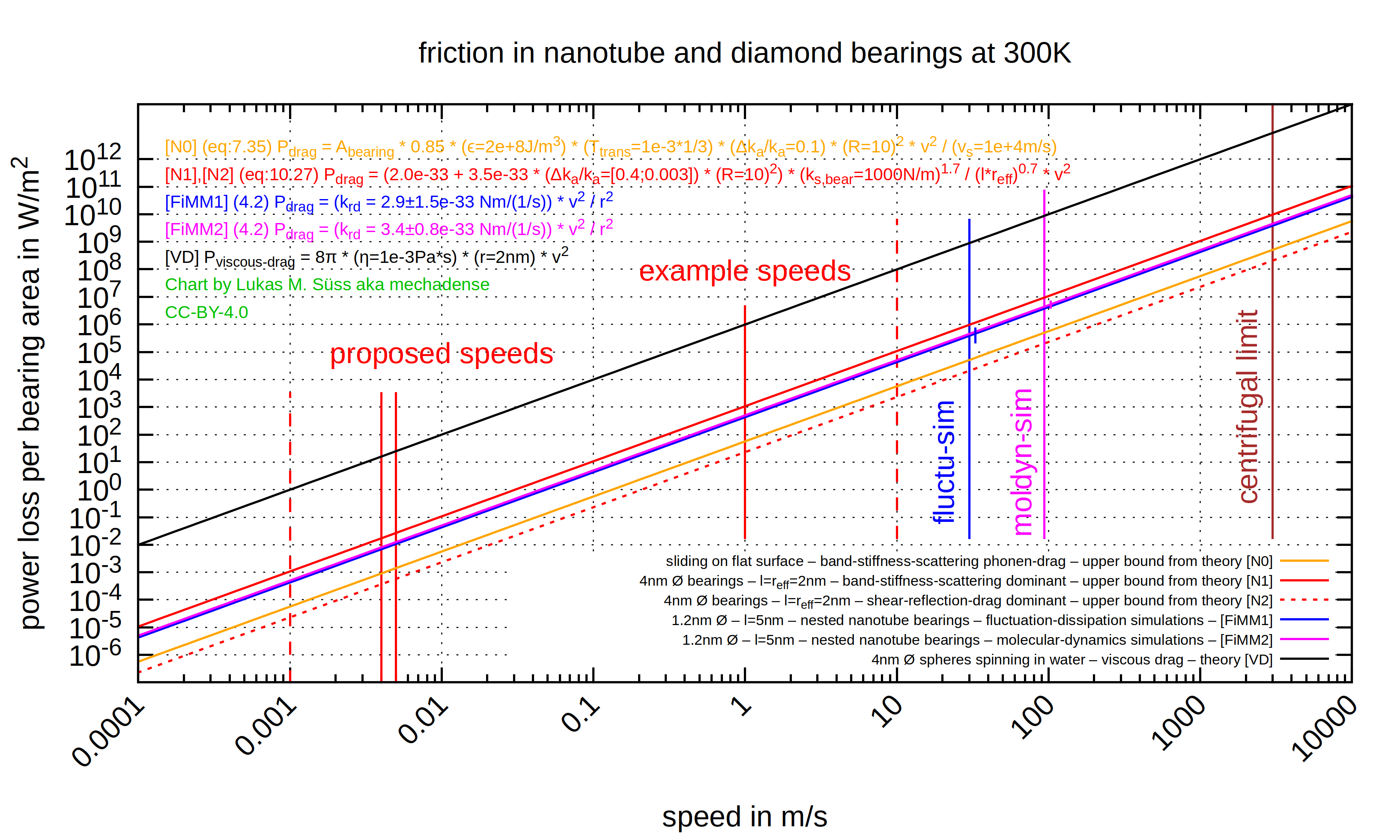
    I wanted to have the results of the paper:
    – [FiMM] Evaluating the Friction of Rotary Joints in Molecular Machines
    and the numbers in:
    – [N] Nanosystems: Molecular Machinery, Manufacturing, and Computation
    in a comparable form (motivation further down).
    So I converted what I found to common units and combined them together into a single plot.
    I got some surprising results:


    Simulation results in [FiMM] exceeding conservative upper bounds in [N]?


    Estimations in Nanosystems [N] are supposed to be highly reliable upper bounds,
    so somewhat accurate simulations delivering values above (or only slightly below)
    the Nanosystems values are a sign for some potential error.


    The two mutually quite consistent nanotube simulations from [FiMM] are
    both quite far (~10x) above Nanosystems upper bound for the flat-surface-case of equal area.
    It could be that flat surface friction is higher than for very small diameter bearings.
    But that much and more? I doubt it.
    (I maybe need to check out the limit for big diameter bearings)


    The upper bound for the diamond bearing case is (as it should be) above the simulations.
    But only by a for Nanosystems quite small margin of very crudely 3x.


    Have I made some error?
    Or is there a genuine issue?
    A review would be appreciated.


    Regarding the lowest friction dashed red line:
    Nanosystems mentions a special trick that could be used to lower friction by a further whopping 1000x.
    (dropping band-stiffness-scattering drag below irreducible remaining shear-reflection-drag – via proper bearing design)
    This one is way below the friction levels in [FiMM] but that's ok since the simulated nanotube bearing does not apply this trick.
    I'm not entirely sure whether I comprehend that trick correctly.
    It is not visually illustrated in Nanosystems.
    More on that later.


    Suprisingly high levels of friction for the name "superlubricity"


    As just one random example picked form the chart there is about 100W/m^2 at 1m/s.
    Compared to what is possible with macroscale ball bearings that's not small. I wasn't really expecting that.
    Guess "superlubricity" really refers more to the complete absence of static friction
    rather than to small dynamic friction.


    Wikipedia page seems not aware of that:
    https://en.wikipedia.org/wiki/Superlubricity
    What's up here?!


    Luckily the scaling law "smaller machinery features higher throughput per volume" saves the day.
    In so far as it allow to do plenty of the obvious solution:
    Going down to lower speeds since "halving speed quarters friction"
    (and distributing speed differences over several stacked interfaced).


    The up to 1000x lower friction trick:


    Nanosystems page 174 bottom (7.3.5.c.):
    "As discussed in chapter 10, Δk_a/k_a can be made small in bearings of certain classes, …"
    Nanosystems page 292 (10.4.6.c.):
    "… For first-row atoms (taking carbon as a model), Δk_a/k_a ≈ 0.3 to 0.4 (at a stiffness-per-atom of 1 and 10 N/m respectively)
    where d_a = 0.25 nm, and ~0.001 to 0.003 where d_a = 0.125nm. This value of d_a cannot be physically achieved in coplanar rings, but it correctly modeles a ring sandwiched between two other equidistant rings having d_a = 0.25nm and a rotational offset of 0.125nm."


    Given Figure 10.9. (page 285 before) I think "coplanar rings" here actually refers to "cocylindrical rings".


    – d_a is the (possibly virtual) interatomic spacing along the bearings circumference
    – k_a is the stiffness-per-unit-area of the bering interface
    – Δk_a is the peak-to-peak variation of this stiffness due to "alignment bands" (spacial corrugation interference periods)


    I totally don't understand how only halving the
    (virtual) inter-atomic spacing can make the friction drop by almost a 1000x ?
    That is: How halving d_a makes Δk_a/k_a go down by a factor of 1000x.
    Anyone any idea?


    Also I wonder if this would work with the offset being applied to atoms that are situated
    further axially along on the same surface if they are (sideways) coupled stiffly enough (like alternating rows).
    That option would remove the hassle of needing to design radially wedged bearings.
    Anyone knows?


    Motivation:

    Showing how the scaling law for throughput is the main factor driving friction losses down.
    And creating awareness about this scaling laws unoverstatable importance.


    I eventually want halfway reasonable friction-loss-numbers for
    an animation visualizing the (IMO much too unknown) scaling law of
    "higher throughputdensity of smaller machinery"
    Preliminary state here:
    YouTube+APM again


    There was an article on Erics former website featuring this scaling law, but
    I can't even find it on the Internet Archive anymore.
    So I started making this animated 3D-model.


    Further plans for making charts that are relevant for nanoengineering:

    I'd like to eventually get to a chart that takes into account desirable deliberate deviation from keeping absolute speeds constant over scales.
    A chart where halving speed comes with a doubling of area (and proportional productive machinery volume) such that overall throughput stays the same.
    This leads to:
    – many parallel lines each for a specific total throughput.
    – linear rather than quadratic lines (half the slope in double-log chart)
    – absolute power loss on the y-axis ~&gt; getting back to powerloss-per-area is seriously confusing I found
    There are a lot of details so I leave that for an eventual later post.


    Transport dissipation losses in soft nanosystems:

    Viscous drag being so much higher is expectable.
    [VD] https://web.archive.org/web/20…om/p/04/03/0322drags.html


    But this does not show inferiority of soft nanosystems in terms of efficiency, as I've initially wrongly assumed.
    What one would want to compare here is diffusion transport.
    But the speed of diffusion transport being distance dependent makes it difficult to compare.
    For a desired diffusion speed this would I presume need assumptions on
    – spacial pit-stop-membrane crossing frequency
    – energy dissipation per pit-stop
    – size of transported particles
    Maybe something to look into …


    Attached:
    My preliminary version of the compiled friction results chart.
    I may eventually publish the gnuplot source to github.

    New video is out since mid February 2022:


    Well, It's just a sneak preview for something
    – with smooth animation from pre-rendering
    – proper example numbers and
    – spoken explanation


    No clue how long till I have something
    at the current pace this goes nowhere …


    Copied over from the video description:


    Here's a sneak preview for a video that I'm planning.*THIS NOT A PROPOSED SYSTEM*It only serves to illustrate an important scaling law that IMO deserves more public awareness.For future cog-and-gear style diamondoid nanotechnology the high surface area of all the many bearings at the nanoscale (causing friction losses) is not a show-stopping problem, as is sometimes assumed. One main reason for that is:A very small volume of productive nanomachinery already suffices for practical levels of throughput.So why is only very little volume of nanomachinery sufficient?Every layer shown in the animation processes the exact same amount of product per time. But the layers get successively thinner.So the lowermost ultra-thin layer with nanomachinery at the very bottom processes the exact same amount of product per time as the macroscale robot in the big fat box at the very top. All layers but the nanomachinery layer at the very bottom can be made optional and stripped away. But even if they are left in they do not contribute all that much to friction. This goes into a rabbit-hole of details ... which I'll omit.But the smaller and smaller robots here operate faster and faster the reader might argue. Well, no. They don't. Note this deceptive fact: While frequencies increase when going down the layers, the absolute speeds actually stay unchanged/constant. Everything operates at the natural frequency for its scale in this illustration here (which is not a proposed system btw).So in summary the teased on *SCALING LAW* reads as follows: **Smaller machinery features higher throughput per volume (higher throughput density). A linear scaling law. Half size means double throughput density.***MATH:* http://apm.bplaced.net/w/index.php?ti...Reviews appreciated.*BONUS:* And if you "buy" lower speed of nanomachinery (absolute speeds not frequencies) by "paying" with a higher quantity (volume) of nanomachinery (keeping throughput constant) then friction losses still fall further. That is because dynamic friction losses scale down quadratically with sliding speed while friction losses scale up only linearly with the quantity (volume) of nanomachinery. Taking this into account one gets closer to an actually proposable system.Keywords:* APM atomically precise manufacturing* diamondoid nanomachineryMusic by SuperLinuxAudioGuru - License CC0https://youtu.be/lxwcNZWLDwQTHE SHOWN ARCHITECTURE IS NOT A PROPOSED SYSTEMIt only serves to illustrate an important scaling law that deserves more public awareness.— — —★ Public APM forum: https://sci-nanotech.com/★ My Twitter: https://mobile.twitter.com/mechadense★ My homepage: https://mechadense.github.io/00.Home-...★ My wiki: http://www.apm.bplaced.net★ Support me: https://www.patreon.com/mechadense

    Regarding the topic of material stiffness:
    I've since cleared up a long held misunderstanding of mine.


    While stiffness indeed shrinks with falling size (to levels that make the softest jelly envious - I'm to lazy to dig up example numbers right now) inertial masses shrink in such a way that they exactly compensate this falling stiffness when speeds are kept constant across scales (or equivalently: when operation frequencies rise linearly with falling size - which is a somewhat natural assumption).


    So problems with mechanical ringing stay unchanged from macroscale to nanoscale. But …


    … But one actually wants to slow down since one both can-afford-to and need-to do so.
    – "afford-to" relates to the enormously beneficial scaling law for troughput-density
    – "need-to" relates to surprisingly high friction-losses-per-area of superlubrication even at moderate speeds
    More on that elsewhere eventually … (more cleared up misunderstandings of mine there)
    Anyways, presumably out of these (here not explained, and in the book Nanosystems not explicitely stated) reasons the typical/majority-of operating speeds of nanomachinery in the book Nanosystems are intentionally proposed quite low at around 4 to 5 mm/s.


    So the macroscopic analogy would be a hypothetical …
    – machinery that one can afford to operate 1000x slower while retaining the same product throughput
    – material with stiffness of diamond but two digit prozentual elasticity before a break
    So much for all those saying/preaching that "things change for the worse" when using cog&gear style nanomachinery at the nanoscale . Availability bias at work …


    So keeping macroscopic prototypes for nanoscale target systems conservative in their assumptions on stiffness despite them being made from very low stiffness plastics seems trivial. Not something to worry about.
    Holds for all but the first assembly level. See next paragraph.
    In fact such prototype systems are so far lower in performance against ringing that it might be problematic in the other way.
    That is: Nanostructures could be made much more filigree.
    Macroscale 3D-printed plastic prototypes may suffer from unavoidable over-engineering.
    While they will still work at the nanoscale they will be far from ideal/optimized.


    Well, low stiffness not being a worry only holds as long as there is no piezomechanosynthesis involved.
    (Piezomechanosynthesis as in tool-tip preparation and the first assembly level from moieties to crystolecules).
    Beefy high-stiffness-from-geometry-structures at the nanoscale are really only needed to counter deflections from thermal motion
    since these deflections are many orders of magnitudes larger than the deflections from machine accelerations at the smallest scales.


    At the second assembly level (assembling from crystolecules to microcomponents) deflections from thermal motions
    are already quite probably pretty much negligible. There is:
    – a large number of parallel acting high stiffness bonds
    – only about kT of energy for the lowest order bending modes of the whole crystoleculear structure (typically many thousands of atoms)
    – compensatability by self centering
    So I wouldn't expect a need to focus on choosing maximally stiff geometries there.
    Well, to be absolutely sure I still need to check actual numbers …


    Side-note: There are other reasons beside stiffness to go for parallel manipulators.
    Like e.g. a larger number of pathways for mechanical motion threading via chains or such.

    University of Oxford:
    "Postdoctoral Research Assistant in DNA Nanotechnology Applied to Molecular Additive Manufacture": link
    (Only applications received before 12.00 midday on 15 June 2018 can be considered.)


    More funding for APM by AMO: link
    ( AMO ... Advanced Manufacturing Office link )


    "Evaluating Future Nanotechnology:
    The Net Societal Impacts of Atomically Precise Manufacturing"
    Steven Umbrello, Seth D. Baum
    Global Catastrophic Risk Institute,
    http://gcrinstitute.org
    (2018-04-28): link


    Meetup group: League of Extraordinary Algorithms -- Special Topic: Molecular Manufacturing (past - was on 2018-05-12) -- link

    Paper title:
    "On the effect of local barrier height in scanning tunneling microscopy:
    Measurement methods and control implications"
    https://doi.org/10.1063/1.5003851


    I'll try to summarize in a reader friendly way.
    (I found abstract and conclusion of this paper not really satisfying.)


    One of the most serious issues with current STM microscopes
    is their tendency to fail on some more severe surface features like e.g.
    chemically highly reactive sites including dangling bonds.


    (Since I've once worked with an STM (omicron) I know that pain all too well.
    Exactly where it gets interesting one gets all those "shadows" where the feedback control fails.)


    A simple formula for the tunneling current in STM's is like follows:
    i = c*V * exp( -d * delta * sqrt(phi) )
    where:
    0) c*V ... some constant
    1) d ... another constant = 10.25 sqrt(eV)/nm
    2) i ... tunneling current
    3) delta ... tunneling gap length in nm and
    4) phi ... arithmetic average between probing-tip and sample work functions


    Logarithmized this equation becomes:
    ln(i) = ln(c*V) -d * delta * sqrt(phi)


    In the usual operation range for the occurring delta values, phi is mostly independent of delta.
    Written in differential form:
    d_phi/d_delta ~= 0


    Thus one can differentiate the logarithmized equation to:
    phi = (d_ln(i)/d_delta)^2


    So from the squared slope of the logaritmized tunneling current one can determine the work function average. Since this value is position dependent one can obtain a local-work-functon-image better known as local-barriere-height (LBH) image.


    Now here's the problem:


    Reversely, varying the current always in the same way, meaning independent of the LBH at the current position, produces different variation amplitudes of delta depending on the local work function. What most current (2018) STMs are using is PI control that uses exactly that position independent constant gain. And this is what regularly gets them into an unstable regime (a regime where the actual current widely detours from desired current) at locations with low LBH. This is leading to the aforementioned "shadows".


    Here's what the papers authors did to solve the issue:


    They superimposed a "high" frequency dithering signal (dither frequency was 4kHz) onto the unprocessed feedback signal such that they could determine the LBH based on the resulting current variations. (This part was not new.)


    Then they use the gained LBH value to continuously (LBH estimation bandwidth was 400Hz)
    re-tune the DC gain of the STM's PI controller. Re-tune the the proportional P part. (PI Feedback bandwidth was 300Hz.)


    As a side-note: They used some alternative implementation of a lock in amplifier including second order band pass filters and first order Lyapunov filters. They write that they have outlined details about that in one of their preceding papers.


    The results:


    (Fig. 5.):
    (1) Significant reduction of the unwanted correlation of the LBH images with the topography images.


    (Fig. 6):
    (2) At the usually wanted and or necessary high gain settings near the stability limit, sudden drops in LBH (like in case of dangling bonds) do no longer lead to PI control breakdown. The old "solution" of reducing the overall gain led to more tip-sample crashes (especially in lithography mode) due to less sensitivity and smaller bandwidth.


    (Note: The shadows are no crashes. They are more like over-retracts. When lowering DC gain to reduce these shadows, this is when one gets crashes.)


    They write that the usual assumption of the "gap modulation method" is that the delta dithering amplitude is constant because the modulating frequency is beyond the controller bandwidth. ("gap modulation method" == established method of feedback dithering for LBH image generation)
    They write that this assumption does not always hold. Especially for fast-scanning high-bandwidth scanners.
    And I take (my interpretation reading between lines) they mean the problem was not solved till now because this problem was overlooked.


    All this was done with big slow macroscopic piezo based STMs.
    (An in house own design STM of Zyvex and an omicron STM for comparison.)


    So we are left to wonder how much this will do for fast and lightweight MEMS based STMs.


    PS: Here's some news coverage with video:
    https://www.nanowerk.com/nanot…ogy-news/newsid=49386.php

    Primary press release: https://www.tum.de/en/about-tu…ses/detail/article/34408/
    Paper (walled): http://science.sciencemag.org/content/359/6373/296
    Video: (long url)
    Direct link to video: https://www.youtube.com/watch?v=K9fuSVaszyg


    I was very much waiting for these news.
    This will go into my list of archived milestones in the incremental path.


    Next up, to widen the data bottleneck, this needs to be electrically parallelized and combined with (nontrivial) nanomechanical demultiplexing.
    All that while reducing self assembly failure rate and further extending and improving improving (the already demonstrated) convergent/hierarchical self assembly capabilities.


    The emergence of unconventional biomineralization research is also a milestone I'm eagerly waiting for.
    (Unconventional in the sense of not trying to recreate strong (but non AP) composite materials like mica but trying to create less strong but more versatile pure and AP single crystals of desired shape.)


    PS: some media coverage:
    nanowerk; nextbigfuture; kurzweilai

    Name: "Mechanical Computing Systems Using Only Links and Rotary Joints"
    (Submitted on 10 Jan 2018)
    by Ralph C. Merkle, Robert A. Freitas Jr., Tad Hogg, Thomas E. Moore, Matthew S. Moses, James Ryley


    https://arxiv.org/abs/1801.03534


    (There was a preceding report: http://www.imm.org/Reports/rep046.pdf)


    Essential points:
    +) extreme simplicity, only two elements, links and and 2D rotary joints
    +) (as the paper says): "All parts of the system can remain permanently connected and yet still provide all necessary combinatorial and sequential logic"


    It is not mentioned in the paper like this but I think the idea (Fig.3) can be interpreted a bit more abstractly as such:
    The locks provide a singular mutual dead center point where one gets an additional "singular DOF".
    (Does "singular DOF" make sense? I mean a point where two DOFs cross and one can switch between the two systems. There might be a relationship to holonomic constraints: https://en.wikipedia.org/wiki/Holonomic_constraints ? Or not.)
    This one additional "singular DOF" allows for temporally decoupling the downstream logic from the upstream logic without actually detaching parts (which would likely cause vibrations), and thus allows for:
    1) "repeated buffer power refresh in a pipeline by clocking" and
    2) "(reversible) latch memory" in sequential logic. (referring low density memory, not particularly to to high density memory like Fig.16)


    3D printing demo models (as suggested in the paper - Fig.22) would be cool, but even pretty simple things (beyond the depicted 3D modeled test part) like a basic one bit full adder (Fig.6) are already pretty darn big in their maximally compressed form (which, I take, is depicted in Fig.6).
    Btw: Even basic universal gates NOR or NAND (NAND Fig.5 is double sized combo with negated logic I think) are already composite structures in this "calculus".
    Naively composing these composites (e.g. to the aforementioned full-adder) without a then following simplification step makes the results even bigger. (It's an uncompressed form).


    Making models by cutting links form bottle plastic (HDPE / PET) with scissor and hole puncher may be viable and cheap.


    Some side-notes / observations:+) IIRC Nanosystems mentions that dissipation from sliding rotation scales worse than dissipation from sliding translation. But I think this is still much better than rod logic.
    +) Friction force and thus dissipation too (dissipated_energy = force * path * friction_coeff) is in first approximation independent of area (at least on the macroscale). So if force is kept constant (not pressure as in the usual case!!) then a bigger superlubricating bearing should perform not much worse than a single sigma bond bearing. Shouldn't it? I'm oversimplifying. I definitely need to more thoroughly re-read the paper "Evaluating the Friction of Rotary Joints in Molecular Machines" Ref[11]
    https://arxiv.org/abs/1701.08202.
    +) IMO the single-sigma-bond-bearings partially destroy the benefit of radiation hardness which the massive links provide (mentioned in intro section 5.1).
    That needs to be quantized.
    +) The current design (Fig.24) with its stark size mismatch between bearings and links feels rather prone to overtones, ringing, sidewards wiggling, ... .
    I could be wrong there.
    +) Maybe the two preceding points are just a matter of optimization focus:
    Minimal dissipation (design as presented - cost in radiation hardness and size)
    Maximal radiation hardness (bigger bearings - cost in dissipation and size)
    Maximal compactness (smaller links - cost in radiation hardness and dissipation due to falling link stiffness)
    +) Flex logic (Fig.23) seems even better for the nanoscale but bad for 3D printed models with quickly wearing high dissipation plastics.
    +) I'm a bit puzzled why they've chosen pushing instead of pulling. (Well it doesn't really matter much.)
    +) The transmission lines move in a reciprocative manner (just like in rod logic) ... (Had to add "reciprocative". I totally love that word.)
    +) Related mechanism: https://en.wikipedia.org/wiki/Whippletree_(mechanism)
    +) Bonus for mentioning Konrad Zuse and his Z1


    I still haven't read all the way through the paper.
    So there's a chance I've missed some important points that I would like to point out especially.


    PS: I was notified about this via a google alert I set up for "atomically precise manufacturing"
    This guided me to: https://boingboing.net/2018/01…s-made-purely-of-joi.html
    Also I found some discussion here: https://news.ycombinator.com/item?id=16129830